RECENT POSTS

Resolved! Virtual machines should encrypt temp disks, caches, and data flows between Compute and Storage resources

Virtual machines should encrypt temp disks, caches, and data flows between Compute and Storage resources

There are multiple ways to encrypt the machines to make them secure. Azure provides the solution by itself to make them encrypt the operating system and virtual machine disk to make them secure. The policy "Virtual machines should encrypt temp disks, caches, and data flows between Compute and Storage resources" was faced by me when I used ISO 27001:2013 in my project. So Here I will give you the solution to solve this policy using portal/bicep and also what condition are required.

The following project will help you to solve the following queries:

  • How to implement encryption on Azure Linux Virtual Machines OS and Disks using Portal?
  • How to implement encryption on Azure Linux Virtual Machines OS and Disks using Bicep?
  • How to implement encryption on Azure Linux Virtual Machines OS and Disks using ARM Templates?
  • How to resolve "Virtual machines should encrypt temp disks, caches, and data flows between Compute and Storage resources" Policy?

Requirement

To implement the policy there are multiple ways but we will discuss here the use of portal and bicep. So to implement the encryption just make sure the following two setting:
  • Encryption at host
  • Enable Ultra Disk Compatibility
  • Azure Disk Encryption for Volume Encryption

Azure Disk Encryption for Volume Encryption

  • Make sure this setting is enabled.
Azure Disk Encryption for Volume Encryption

Encryption at host, Enable Ultra Disk Compatibility

Method 1: Disable during creation of Virtual Machines

Enable Ultra Disk compatibility, Encryption at host

Method 2: Disable after Creation of Virtual Machines

  • Turn off the Virtual Machine
  • Go to the following directory: 
    • VM > Disks > Additional Settings
Enable Ultra Disk compatibility, Encryption at host
  • Disable Both of these options.
Enable Ultra Disk compatibility, Encryption at host

Implementation

To implement the OS Disk, you can use both the portal and bicep. 

Portal: To implement the solution using portal go to the following window and then add it. 

Note: To implement it just make sure virtual machine is running
  • To implement the solution go to the following window and open the addition setting:
Enable Ultra Disk compatibility, Encryption at host
  • Then select the key from key vault which you will have to generate in key vault
Virtual machines should encrypt temp disks, caches, and data flows between Compute and Storage resources

Bicep: To implement the solution using bicep
  • Add the following extension with some parameters.
@description('Encryption of VM Disk')
resource dikskEncrypt 'Microsoft.Compute/virtualMachines/extensions@2018-10-01' = {
  name: 'AzureDiskEncryptionForLinux'
  parent: virtualMachine
  location: location
  properties: {
    publisher: 'Microsoft.Azure.Security'
    type: 'AzureDiskEncryptionForLinux'
    typeHandlerVersion: '1.1'
    autoUpgradeMinorVersion: true
    forceUpdateTag: '1.0'
    settings: {
      EncryptionOperation: 'EnableEncryption'
      KeyVaultURL: '<Enter Keyvault URL Here>'
      KeyVaultResourceId: '<Enter Keyvault Resource ID>'
      KeyEncryptionAlgorithm: 'RSA-OAEP'
      VolumeType: 'All'
      KeyEncryptionKeyURL: '<Enter Keyvault URL with version>'
      KekVaultResourceId: '<Enter Keyvault Resource ID>'
      SequenceVersion: '<Enter Sequence Version: Detail>'
    }
  }
}
  • The bicep has some parameters which needs to be enter, for "KeyEncryptionKeyURL" the url should be in this following format.
https://<Keyvault Name>.vault.azure.net/keys/<Encryption Key Name>/<Encryption Version Name>

That's all to do the job. Keep me update in case you find the issue. 🙂 

Underwater Drone For Surveillance - Architecture

Underwater Drone For Surveillance - Architecture


INTRODUCTION

Underwater drone is a smart device with the use of sensors in lower cost to capture the beauty of a small pound and gather it from different angle, which human eye is unable to see.

FEATURES

Drone is extremely easy to operate due to its internal design and it has multiple protections which a drone can face under the water in normal conditions. The drone has the ability to provide a live feed and its smart structure makes it to operate in 360 degree and also give the life feed to screen.

CAMERA

There is a glass in front of the drone from where a camera is installed which helps to monitor the live view under the water without effecting from water. The glass also helps to cut through the water.

Smart Balancing

The drone has a smart balancing system to itself. The sensor automatically operates the engine without affecting anything and keeps it at a specific angle in all three directions.

Object Detection

The drone can have protection from obstacles. In case of any object in front or beneath the done, it stops the engine to move in that direction.

Waterproof

The whole operating system is made of electrical and it is difficult to operate these appliances underwater. In drones most of the sensors are waterproof but the rest of the design uses the sealing in the body to avoid water interaction with the internal system.

VISUAL

Underwater Drone For Surveillance - Architecture

Detail

The features of drones may be limited but their internal design requires special attention. The internal structure is a combination of different devices, most of them are seniors and their spatiality is that they all fit for their role with the drone. As you can see in the image, we have multiple sensors but some of them are hidden inside. Let me describe what each device does in the drone.

Motors

Underwater Drone For Surveillance - Architecture
FANS

In the drone, there is only one major CPU that controls all the functionality. The drone processor uses timely loops to control the motors and sensors keep running in the background to provide the continuous signal. The main drone functions are its movement. To make the drone moveable, waterproof motors have been used. The motors are attached to further fans and servo motors. The combination of servo and other motors helps it to move in all directions without any issue. The motors use a driver which makes the motors move in both directions on the basis of the incoming signals.

Gyroscope

The motor movement receives from remote which uses sound waves to send a signal but the problem here is a little different. When the remote sends the signals to the drone then its motors start operating as it has been set on different signals. The problem here is the drone direction can also affect water flow. To avoid the effect of water on drone movement a gyroscope sensor has been used to control that. The sensor keeps the drone at a specific angle. Every time the drone losses its position by water flow, the sensor makes the motors move it back to its specific point. The basic function of the gyroscope is to tell all of its angles in all 3d planes. The smart programming helps to automatically operate the motors in case of a change in angle from a specific point.

Underwater Drone For Surveillance - Architecture
Gyroscope

Camera Feedback

The camera part is one of the most amazing parts of the drone due to its calculated design. The camera is hidden behind the glass, from which it takes a full front view. The glass protects the camera from water and its curvedness makes it cut through the water. That flow of drones has a much lower effect on drones’ motors. The camera captures the beautiful movements underwater and sends them to the surface where it is canalized to the screen which is set on the remote.  The live view of the screen can control the drone but there Is a little bit of latency issue in the whole process. The millisecond's difference puts the drone in a risky state. This problem is solved by some other sensors.

Ultrasonic Sensors

There are two waterproof ultrasonic sensors attached to the drone. The one is on the head of the drone which checks the obstacle in the front direction and the other one is attached beneath the drone. It checks the obstacle under the drone. Both sensors help to avoid obstacles in case a user is unable to view on the screen. Both of these sensors are waterproof and specially designed to operate underwater. Besides these sensors, there are some others, especially in the drone. There are other two sensors that help to decide the underwater environment.

Underwater Drone For Surveillance - Architecture
Sensor

Temperature Sensor

The temperature sensor helps to avoid the high and low temperature issue. The temperature sensor it helpful when an animal is near to the drone. It can calculate the water temperature. The temperature sensor only helpful in close interaction of an animal but the other sensor known as pressure sensor solve the other issue.

Pressure Sensor

The pressure sensor helps to calculate the pressure of the water. In case of water pressure changes then it can be received by the pressure sensor. The pressure sensor has a higher chance of measuring animal presence from a larger distance than the temperature sensor. So, in that case, a drone camera can be moved to the other direction to view the animal. That is really helpful to capture the movement and can also be used to save the drone from larger size animals like whales. The pressure sensor not only works as a pressure sensor. It also works as a temperature sensor too. The usage of two temperature sensors helps to minimize the error by getting two readings.

Lights

There are two led lights are attached to the drone at the front. These lights help to clear the darkness coming in the camera. The lights give the proper view to the camera and help to capture the best visuals. The led button is present on the remote. So, in case to turn off the led the button will be helpful. The led and drone will be fully controlled through

Monitoring

The monitor part is very helpful for drone movement but it has some specific limitations. In which the main one is the time delay between camera and screen due to the low latency rate. So, to operate the drone always keep in mind that it has sensor values that show on the top of the screen. Always keep an eye on the top of the screen, that is really helpful.

Drone Body

The body of the drone is fully optimized according to the water flow and sensor requirements. The body helps to operate the engine in a smart way. Especially it helps to make a path in the water and also helps in standing on the water in case of water. There will be water resistance on the drone but the design of the body minimizes it in many ways.

WARNINGS


Underwater Drone For Surveillance - Architecture

Don’t open the drone, unless you have knowledge about its internal structure. It has been sealed to protect itself from water.

Don’t place the drone in hot water the other camera and ultrasonic sensors could be affected by high temperature

Keep an eye on the sensor values to operate efficiently.

 Note: The Drone image and 3d file were taken over the internet just to represent the project.

Window 10 pastes random hashed string [Solved]

Window 10 pastes random hashed string  [Solved]
Window 10 pastes random hashed string  [Solved]

There are a lot of viruses in the windows but what if your operating system has a virus by default. You may be thinking about how a new installation of a window can have a virus? Yes, you are right. A few days back I found an issue on my windows 10 during copy-paste. Some of my links which are cached in my browser, I was unable to copy-paste. Whenever I try to copy them I get a hash or we can say an encrypted text, which I was unable to understand. I verified it from the windows 10 clipboard by enabling it. Here's the image of the clipboard.

w10 clip board image
W10 Clip Board

I was unable to take the screenshot during the virus. So my bad. But the point is I am writing this article is because I want to make sure that everybody could understand this issue and will be able to avoid it. First, we will learn from where the issue came from, and second what is the solution to it.

How did it come to my computer?

I had an old habit of installing a window with pre-activation and pre-installed  MS Office. When I installed the pre-modified operating system I found the issue in my copy-paste after a week. I searched over the internet but then there was nothing specified. After that, I searched the task manager and found these two items in it, which have the same logs.
Window 10 pastes random hashed string  [Solved]
svhost.exe


Window 10 pastes random hashed string  [Solved]
logui.exe

These two services are actually the virus and were installed on the computer during the installation of windows.

Solution

Right now I don't have any proper solution but these three tricks could work for you.

1. Close Them

By selecting these services and clicking on "End Task" you will find a temporary solution to the copy-paste issue. 

2. Window Installation

It's really bad to lose the data to the hacker. So, just download the original ISO of OS and then install it from the scratch. This is the permanent solution. This way you will have the time to organize data to different harddrives.

3. Remove it

I am pasting here a third method that I found on the internet. So it is not being verified but I am pretty sure it could work. Here's the link: Click to Go

In case you need further help. Feel free to contact me over the social media or comment box.

10 Helpful PCB Assembly Tips for Product Developers

10 Helpful PCB Assembly Tips for Product Developers

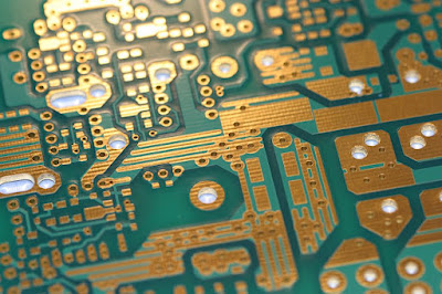
PCB (Printed Circuit Board) is a basic thing in any electronic circuit. The whole board is responsible for communication between different components. The product developers are a final step of product design but avoiding some steps can lead to serious problems. Assembling requires some special steps to follow. These steps are common in designing and developing PCB but the developer’s intention is required to these steps. Otherwise, the issues are formable easily. The components on the PCB needs to attach with specific measurement and protocols. To assemble every component the PCB developers, need to focus on some points:

1. Consulting with Designer

There are different kinds of companies for PCB designing with assembling. Every company should communicate with its buyer from the start, even before PCB designing. Almost every company which offers the PCB assembling also designs the PCBs. Some buyers prefer to make it from their selective Designers. In those cases when the Designer is from within or outside the company, he/she should get the guideline from its developer. Especially for which component developers have and which he prefers to use. In that case, the assembling process becomes easy and assembler doesn’t have to struggle for available components.

10 Helpful PCB Assembly Tips for Product Developers

2. VIAS

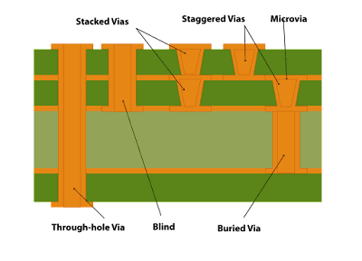
In every PCB, the Developer will get vias that are used to connect the different layers for proper path. The larger number of vias aren’t good for PCB. They are alike drill points on the PCB but their basic purpose is the connection within layers. Before starting the assembling of components on the PCB try to fill out the vias otherwise, it could cause confusion between the components drill points and itself.

10 Helpful PCB Assembly Tips for Product Developers


3. COMPONENTS GUIDELINES

In the case of handmade assembling, Every PCB Designers provide the silkscreen on the PCB for each component placement. In some cases, PCB loses its silkscreen for some components. The only way to make it clear for each component use the 3d model of the PCB design, which can be generated through any PCB designing software.

10 Helpful PCB Assembly Tips for Product Developers

4. SMART SELECTION & PLACEMENT

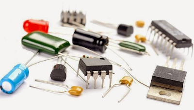
To start the assembling collect all the components from the BOM file. The components’ collection will be a major step and should be from the BOM file otherwise it could cause problems later. The components come from different manufacture with internal design. Try to select the less heat producer and cheap components. This will help in reducing costs and make the PCB efficient. Sometimes the lowering the cost could cause a lowering in quality. So, always contact the buyer and focus on his intention’s requirements. The placement of components smartly can also solve multiple issues.

10 Helpful PCB Assembly Tips for Product Developers

5. SMD/SMT COMPONENTS

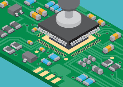
Whenever the PCB has only SMD components then start from the smaller ones. In SMD components the 0602 model of the components is preferable due to their average size. The other components are also useable but the model 0602 and larger than itself are best for PCB.

10 Helpful PCB Assembly Tips for Product Developers

6. THT COMPONENTS

Some PCB with high load only contains THT Components. In that case, the components need to place on a single side. The use of a single layer is only possible in THT components only because of their drilled connection. The components on the single side will make the PCB safer and its height will also become lower and manageable. Try to place the smaller sized components first in the THT placement. In THT the components could overlap easily. The problem can be avoided by changing the layer of the component. If it can’t be avoided then try proper protection between overlapped components.

10 Helpful PCB Assembly Tips for Product Developers

7. PLACEMENT OF Mixed Components

In-circuit boards most of the components could be SMD/SMT. To start the assembling of PCB the SMD components need to place first on the PCB. The SMD components will have a smaller size, and they will be hard to connect when THT components are already been placed. Both SMD and THT components are Larger size components. In PCB assembling try to start from the small components and then move towards the larger components. In case of larger component keep moving from the center towards the border. Even if it is possible, try to talk with the designer for placing the larger components at the border. This will save the pick and place the time of the developers.

10 Helpful PCB Assembly Tips for Product Developers

8. HEAT PROBLEM

The heating factor is one of the problematic factors for PCB. The excessive heat-producing components should not interact with each other and need to place far away from each other. They could harm other components just by excessive heat. This issue comes mostly in THT components and also forgets the single-layer tip for that case.

10 Helpful PCB Assembly Tips for Product Developers

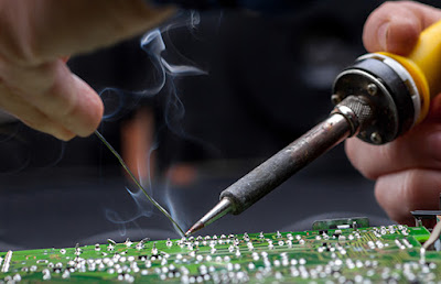
9. SOLDERING

It is the final step in the PCB assembling for developers. In soldering first, try to use the minimum solder as much you can. This will help in reducing heat and short circuit between components. During soldering avoid pad share and heat interaction between components. Therefore, always place the component where it has been marked by the Designer. Heat interaction from kavia could burn some components easily.

10 Helpful PCB Assembly Tips for Product Developers

10. SOLUTIONS OF MISTAKES

First, try to avoid mistakes in attaching components. Even, if you made a mistake then don’t try to use the force to remove the components. Try to use the proper equipment to solve any mistake. If you don’t have specific equipment for mistakes you have done then solve them with a proper protocol. Just try to avoid the use of force on the PCB. This could disconnect the trace of the PCB which can be costly.
Sometimes the connections between components and PCB feel connected but in reality, they aren’t connected. To avoid this mistake, try to verify them after their assembling. The final problem most of the PCB creates is that the remains of solder or the small wires on the PCB or between the component, which can cause problems. Try to avoid it, otherwise short circuits can happen and the whole PCB could become waste with its components.

The above 10 tips won’t only solve the Assembling issue developers face normally; it will also help them to design the best PCB for your buyer with lower cost and timely.

How to Control Internet Speed with Software?


- The following software selfishnet is a public software that can be used in many LAN connections to control the speed.

Selfish net is the best speed controller for the internet through PC or Laptop. Selfish net is free software that allow users to become selfish in case of the internet. To control the internet speed, follow the following steps to control the internet speed using selfishnet:
-Download the Driver first for internet speed controller (Selfishnet) -Then Install the drivers first. -After that run the Selfish net (Internet Speed Controller)
-The control the internet speed as shown in the video.


Video Tutorial

Opposed Piston Engine (High Quality)

pistonheads  opposed  car engine  types of engine  gdr  piston cylinder  single cylinder engine  ecomotor  pistonmachine  2 stroke diesel  piston engine  opposite of oppose  most powerful car engine  different types of engines  opposed piston engine  achates power  opposite of efficient  car engine types  engine crankshaft  car piston  engine cylinder  automobile engine  reciprocating engine  subaru engine  car cylinder  ecomotors  engine efficiency  small engine cars  w engine  piston motor  opoc  piston power  unusual engines  piston stroke  enginetech pistons  cylinder motor  opoc engine  car engine types list  engine cylinder hone  highest rpm engine  new engine design  inline 8 engine  internal combustion engine efficiency  most powerful 4 cylinder  2 stroke engine animation  v32 engine  how does a piston engine work  16 cylinder engine  sleeve valve  single stroke engine  patop  16 valve engine  largest car engine  flat 12 engine  ops engines  most powerful engine ever built  10 cylinder cars  five cylinder engine  piston engine working  10 cylinder engine

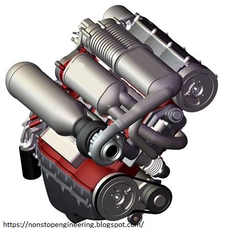
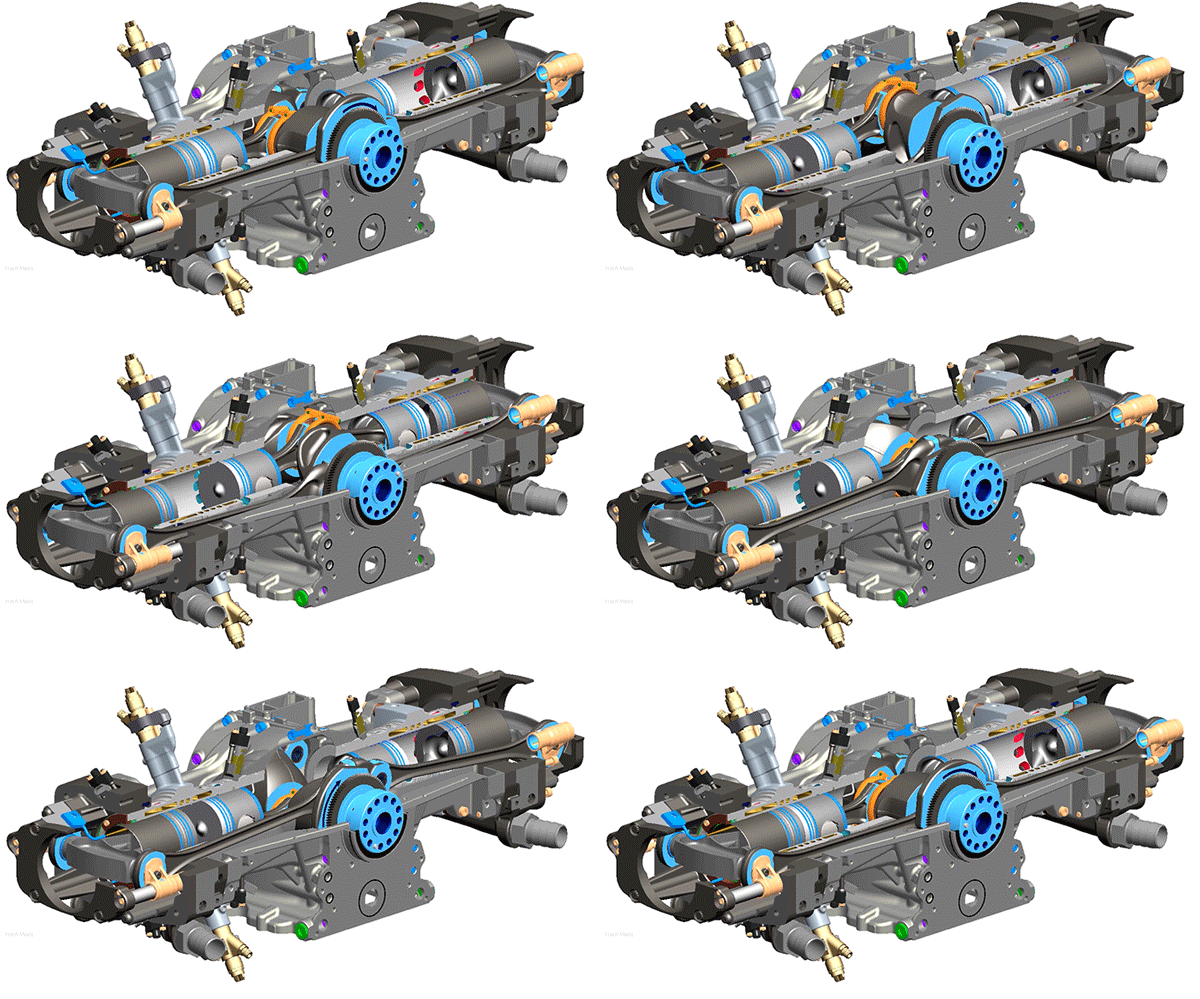
An opposed-piston engine is a reciprocating internal combustion engine in which each cylinder has a piston at both ends, and no cylinder head. In 1882 James Atkinson developed the Atkinson cycle, a variant of the four stroke Otto cycle. The first implementation of this was arranged as an opposed piston engine, the Atkinson differential engine

Two-stroke combustion cycle:
  • A two-stroke engine produces twice as many power strokes per revolution as its four-stroke equivalent. This advantage leads to smaller displacement engines for similar performance, and lower in-cylinder pressure to lower emissions compared to four-stroke conventional engines.
  • In the past, these advantages were balanced by some well-documented shortcomings of two-stroke engines, which limited their scope of use. High hydrocarbon emissions (due to carburetion and over-scavenging) and excessive oil consumption (due to oil-fuel mixing in spark-ignition engines and port oil ejection in compression ignition, direct fuel injection engines) are difficult issues to tackle in these type of engines.
Two-Stroke Diesel Engine
  • The engineers and scientists started Achates Power in 2004 with the audacious idea that innovation and modern technology could transform the proven and record-setting two-stroke opposed-piston engines of the past into the clean and efficient engines of the future.
  • This advantage reduces the fuel used per cycle, resulting in shorter and leaner combustion for optimally phased energy release – all enhancing engine efficiency.
  • Achates Power’s extensive prototyping capabilities and state-of-the-art test facilities are instrumental to confirm at every step the validity of our analytical approach and results.
  • The proprietary cylinder and piston designs achieve unprecedented improvements in combustion efficiency and oil consumption to meet the most stringent emissions regulation. In conjunction with the thermal efficiency advantage inherent to opposed-piston engines, our designs realize significant reductions in fuel consumption over conventional four-stroke compression ignition engines. Based on its unique technology, Achates Power is creating clean, more fuel efficient and lower cost engines for the 21st Century.
Compression Ignition Engine:
Compression ignition engines achieve superior thermal efficiency by the virtue of their higher expansion ratio, inherent fuel-lean combustion and reduced pumping losses.
Although the very first compression ignition engine, designed by Rudolph Diesel in 1894, ran on pure peanut oil, today’s compression ignition engines rely on diesel fuel, thanks to its unique combination of qualities:
  • Energy dense, takes less volume and weight in vehicles
  • Clean, with the recent introduction of ultra-low sulphur diesel fuel
  • Widely available, throughout the world
  • Most cost-effective, in the current economic conditions
Compression ignition with diesel fuel is therefore the combination of choice for the commercial transportation of goods and people on road, rail and water. In fact:
  • In the US, 25% of the fuel used by cars, trucks and buses is diesel fuel
  • In China and India, diesel represents 2/3 of the fuel used for road transportation
  • One out of two passenger cars registered in Europe is compression ignition/diesel powered
Improving further the efficiency of compression ignition engines will reap huge environmental and economic benefits.
And when the cost to use fossil fuels becomes too high, improved compression ignition engines will be ready for the renewable fuels of tomorrow. Already, in 2008, the U.S. produced 691 million gallons of biodiesel(3). Second generation renewable compression ignition fuels from soybeans, biomass, algae and other sources promise that more efficient compression ignition engines are key to a cleaner and safer future for transportation.

Working Diagram: 


pistonheads  opposed  car engine  types of engine  gdr  piston cylinder  single cylinder engine  ecomotor  pistonmachine  2 stroke diesel  piston engine  opposite of oppose  most powerful car engine  different types of engines  opposed piston engine  achates power  opposite of efficient  car engine types  engine crankshaft  car piston  engine cylinder  automobile engine  reciprocating engine  subaru engine  car cylinder  ecomotors  engine efficiency  small engine cars  w engine  piston motor  opoc  piston power  unusual engines  piston stroke  enginetech pistons  cylinder motor  opoc engine  car engine types list  engine cylinder hone  highest rpm engine  new engine design  inline 8 engine  internal combustion engine efficiency  most powerful 4 cylinder  2 stroke engine animation  v32 engine  how does a piston engine work  16 cylinder engine  sleeve valve  single stroke engine  patop  16 valve engine  largest car engine  flat 12 engine  ops engines  most powerful engine ever built  10 cylinder cars  five cylinder engine  piston engine working  10 cylinder engine

➨ Apparently it can have better thermodynamic properties which leads to better fuel efficiency. There are a bunch of different tradeoffs with maintenance and engine size too, but it really depends on the specific model.

ARC FLASH Hazard - Flashover

electrical safety  electric arc  nfpa 70e  arc flash  flash electronics  arc flash study  what is arc  cal flash  arc flash suit  arc flash calculator  arc blast  arc flash video  arc flash face shield  arc blast video  ieee 1584  arch flash  nfpa 70e handbook  osha electrical safety  flash label  40 cal arc flash suit  csa z462  arc blast definition  arc flash coveralls  what is arc flash  electrical arcing occurs when  flash hazard  flash arch  electrical safe work practices  salisbury arc flash  arc flash causes arc flash shirts  arc flash burns  arc flash boundary calculation  prohibited approach boundary  arc flash gloves  arc flash injuries  arc flash protective clothing  flash required  electrical safety training  arc flash accident  arc suit  arc flash temperature  osha arc flash requirements  arc flash explosion  nfpa 70e arc flash table  arc flash rating chart  safety flash  flash can  arc flash training online  electrical explosion  welding arc flash  arc flash youtube  incident energy  arc flash definition  ieee 1584 pdf  flash protection  electrical flashover  arc flash training requirements  electric flash  arc flash ppe chart  electrical safety  electric arc  nfpa 70e  arc flash  flash electronics  arc flash study  what is arc  cal flash  arc flash suit  arc flash calculator  arc blast  arc flash video  arc flash face shield  arc blast video  ieee 1584  arch flash  nfpa 70e handbook  osha electrical safety  flash label  40 cal arc flash suit  csa z462  arc blast definition  arc flash coveralls  what is arc flash  electrical arcing occurs when  flash hazard  flash arch  electrical safe work practices  salisbury arc flash  arc flash causes arc flash shirts  arc flash burns  arc flash boundary calculation  prohibited approach boundary  arc flash gloves  arc flash injuries  arc flash protective clothing  flash required  electrical safety training  arc flash accident  arc suit  arc flash temperature  osha arc flash requirements  arc flash explosion  nfpa 70e arc flash table  arc flash rating chart  safety flash  flash can  arc flash training online  electrical explosion  welding arc flash  arc flash youtube  incident energy  arc flash definition  ieee 1584 pdf  flash protection  electrical flashover  arc flash training requirements  electric flash  arc flash ppe chart

We know that when two conductors are separated and a strong enough field is present between them, arcing occurs. An arc flash is the uncontrolled release of energy when a phase conductor comes into contact with ground or two phase conductors get shorted.
It becomes a hazard when a large enough energy is released in a short enough duration of time. 

➤ Arc flash is most likely to occur during maintenance activities, when a person might accidentally short two points at different potentials.

IEEE 1584 – Guide for performing arc flash hazard calculations and calculation of incident energy.

  • Category 0: 0 - 1.2 calories/cm2
  • Category 1: 1.2 - 4 calories/cm2
  • Category 2: 4 - 8 calories/cm2
  • Category 3: 8 – 25 calories/cm2
  • Category 4: 25 - 40 calories/cm2
➠ The first line of defence to any hazard is by engineering solutions to minimize the likelihood or consequence of the event occurring.
➠ Arc flash incident energy at a point is mainly dependent on three things – fault current, fault duration and distance of that point from the point of fault.
➠ To minimize fault current, we can have fuses. Protection settings can be set to low to minimize the tripping time thus limiting the fault duration (although this may result in false trips). 
➠ We can reduce the incident energy (say at a point outside a MCC) by providing ‘other means’ for the arc flash energy to get dissipated. So, if we provide a vent on top of a MCC, the arc flash energy has more space to dissipate energy than just going straight out. This would reduce the arc flash boundary (defined as the point at which there is a 50% chance for an unprotected person to get 2nd degree burns).

The object of this exercise is to raise your awareness of arc flash hazard.

  • If you leave equipment alone it is unlikely to arc, and due to probability, if it does, it is most likely that anybody is there.
  • You are right, arc flash is more likely to happen when individuals are there, because of the very activities they are performing, be it because they cause a short directly, or because there is a faulty component which is disturbed by their activities.
  • First line of defence is not to work on or near live equipment
  • Second line of defence is in the design as you can never design out the hazard, only reduce it.
  • Last line of defence is PPE.
  • I was at an ABB Seminar the last couple of days and I came across this:
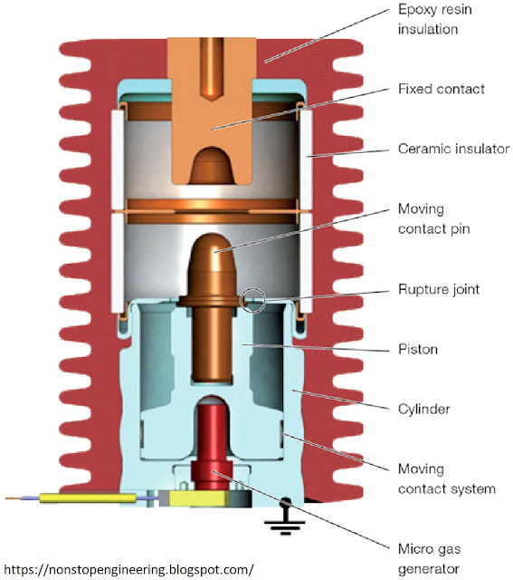
  • Ultra-Fast Earthing Switch (UFES) – It is a sacrificial device to protect equipment in the event of an arc fault. What this essentially does is convert the arc fault into a “bolted” fault, by connecting the phase to earth in 2ms, so that fault current flows through this device instead of the actual fault location. It has a micro-gas generator (which are also used to inflate air bags in vehicles), which ruptures, resulting in the moving contact travelling like a bullet to bond with the fixed contact and created a bolted fault.

➤The device costs around $10k and the replacement cost is somewhere around $4K. Probably a lot cheaper than having to replace the whole switchgear after an arc fault occurs.

RFID CARD READER WITH ARDUINO, RFID-RC522 and LCD 16x2


Radio-frequency identification (RFID) uses electromagnetic fields to automatically identify and track tags attached to objects. The tags contain electronically stored information. Passive tags collect energy from a nearby RFID reader's interrogating radio waves. Active tags have a local power source such as a battery and may operate at hundreds of meters from the RFID reader. Unlike a barcode, the tag need not be within the line of sight of the reader, so it may be embedded in the tracked object. RFID is one method for Automatic Identification and Data Capture (AIDC).
RFID tags are used in many industries, for example, an RFID tag attached to an automobile during production can be used to track its progress through the assembly line; RFID-tagged pharmaceuticals can be tracked through warehouses; and implanting RFID microchips in livestock and pets allows positive identification of animals.
Since RFID tags can be attached to cash, clothing, and possessions, or implanted in animals and people, the possibility of reading personally-linked information without consent has raised serious privacy concerns. These concerns resulted in standard specifications development addressing privacy and security issues. ISO/IEC 18000 and ISO/IEC 29167 use on-chip cryptography methods for un-traceability, tag and reader authentication, and over-the-air privacy. ISO/IEC 20248 specifies a digital signature data structure for RFID and barcodes providing data, source and read method authenticity. This work is done within ISO/IEC JTC 1/SC 31 Automatic identification and data capture techniques.
COMPONENTS:
  • RFID RC-522
  • ARDUINO UNO
  • LED
  • BUZZER
  • JUMPPER WIRES
  • BATTERY (9V WITH CAP)
  • PLUG (5 x 2.1)
  • LCD (16 x 2)
  • ADDITIONAL CONNECTION PINS
  • RISISTANCE (220 ohm) (x 2)
  • VARIABLE RESISTOR (10 K)
CIRCUIT DIAGRAM:


ARDUINO CODE:
  • /*------------------------------------------
  •   RFID CARD READER 
  •   By https://nonstopengineering.blogspot.com/
  •   Using Arduino,RFID-RC522 and LCD 16x2
  •   ------------------------------------------*/

  • #include <EEPROM.h>  //Library To read and write PICC's UIDs from/to EEPROM
  • #include <SPI.h>      //Library  RC522 Module uses SPI protocol
  • #include <MFRC522.h> //Library  RC522 Module
  • #include <LiquidCrystal.h> //Library  for LCD Display

  • boolean match = false; // initialize card match to false
  • boolean programMode = false; // initialize programming mode to false
  • int successRead; // Variable integer to keep if we have Successful Read from Reader
  • byte storedCard[4];   // Stores an ID read from EEPROM
  • byte readCard[4];           // Stores scanned ID read from RFID Module
  • byte masterCard[4]; // Stores master card's ID read from EEPROM
  • #define SS_PIN 10
  • #define RST_PIN 9
  • MFRC522 mfrc522(SS_PIN, RST_PIN);  // Create MFRC522 instance.
  • LiquidCrystal lcd(7, 6, 5, 4, 3, 2); //Initializing LCD PINS as (RS,EN,D4,D5,D6,D7)
  • void setup() {
  •   // put your setup code here, to run once:
  •   Serial.begin(9600);  // Initialize serial communications with PC
  •   lcd.begin(16, 2);    //Initializing LCD 16x2
  •   pinMode(8, OUTPUT);  //LED and Buzzer PIN OUT
  •   SPI.begin();           // MFRC522 Hardware uses SPI protocol
  •   mfrc522.PCD_Init();    // Initialize MFRC522 Hardware
  •   mfrc522.PCD_SetAntennaGain(mfrc522.RxGain_max);
  •   if (EEPROM.read(1) != 1) {  // Look EEPROM if Master Card defined, EEPROM address 1 holds if defined
  •     Serial.println("No Master Card Defined"); //When no Master Card in Your EEROM (Serial Display)
  •     Serial.println("Scan A PICC to Define as Master Card");
  •     lcd.clear();
  •     lcd.setCursor(0, 0);
  •     lcd.println("SET MASTERCARD   "); //When no Master Card in Your EEROM (LCD Display)
  •     lcd.setCursor(0, 1);
  •     lcd.println("SCAN A PICC....."); //Scan any RFID CARD to set Your Master Card in Your EEROM (LCD Display)
  •     delay(1500);
  •     do {
  •       successRead = getID(); // sets successRead to 1 when we get read from reader otherwise 0
  •     }
  •     while (!successRead); //the program will not go further while you not get a successful read
  •     for ( int j = 0; j < 4; j++ ) { // Loop 4 times
  •       EEPROM.write( 2 + j, readCard[j] ); // Write scanned PICC's UID to EEPROM, start from address 3
  •     }
  •     EEPROM.write(1, 1); //Write to EEPROM we defined Master Card.
  •     Serial.println("Master Card Defined");
  •     
  •   }
  •   Serial.println("Master Card's UID");
  •   for ( int i = 0; i < 4; i++ ) {     // Read Master Card's UID from EEPROM
  •     masterCard[i] = EEPROM.read(2 + i); // Write it to masterCard
  •     Serial.print(masterCard[i], HEX); //Master Card only view in serial
  •      Serial.println("Waiting PICCs to bo scanned :)"); 
  •   }
  •   //WAITING TO SCAN THE RFID CARDS:
  •   Serial.println("");
  •   Serial.println("Waiting PICCs to bo scanned :)");
  •   lcd.clear();
  •   lcd.setCursor(0, 0);
  •   lcd.println("WAITING         ");
  •   lcd.setCursor(0, 1);
  •   lcd.println("FOR PICC....     ");
  •   delay(1500);
  • }
  • void loop() {
  •   lcd.clear();
  •   lcd.setCursor(0, 0);
  •   lcd.print("      SWIPE");
  •   lcd.setCursor(0, 1);
  •   lcd.print("    YOUR CARD");

  •  /* 
  •  if (digitalRead(BUTTON) == HIGH);                     //To Delete the EEROM USE the below command just run it
  •   {
  •   // for (int i = 0 ; i < EEPROM.length() ; i++) {
  •   // EEPROM.write(i, 0);
  •   // }
  •   // }                                     */
  •   do {
  •     successRead = getID(); // sets successRead to 1 when we get read from reader otherwise 0
  •     if (programMode) {
  •       // Program Mode cycles through RGB waiting to read a new card
  •     }
  •     else {
  •    }}
  •   while (!successRead); //the program will not go further while you not get a successful read
  •   if (programMode) {
  •     if ( isMaster(readCard) ) {  //If master card scanned again exit program mode
  •       Serial.println("This is Master Card");
  •       Serial.println("Exiting Program Mode");
  •       lcd.clear();
  •       lcd.setCursor(0, 0);
  •       lcd.print("EXITING FROM");
  •       lcd.setCursor(0, 1);
  •       lcd.print("MASTERCARD MODE");
  •       delay(2000);
  •       programMode = false;
  •       return;
  •     }
  •     else {
  •       if ( findID(readCard) ) { //If scanned card is known delete it
  •         Serial.println("I know this PICC, so removing");
  •         lcd.clear();
  •         lcd.setCursor(0, 0);
  •         lcd.print("AVAILABLE!");
  •         lcd.setCursor(0, 1);
  •         lcd.print("SO DELETING.....");
  •         delay(5000);
  •         deleteID(readCard);
  •         Serial.println("-----------------------------");
  •       }
  •       else {                    // If scanned card is not known add it
  •         Serial.println("I do not know this PICC, adding...");
  •         lcd.clear();
  •         lcd.setCursor(0, 0);
  •         lcd.print("Card no:");
  •         lcd.setCursor(0, 1);
  •         lcd.print(readCard[0], HEX);
  •         lcd.print(readCard[1], HEX);
  •         lcd.print(readCard[2], HEX);
  •         lcd.print(readCard[3], HEX);
  •         lcd.print(readCard[4], HEX);
  •         delay(4000);
  •         lcd.clear();
  •         lcd.setCursor(0, 0);
  •         lcd.print("NOT AVAILABLE");
  •         lcd.setCursor(0, 1);
  •         lcd.print("SO ADDING.......");
  •         delay(5000);
  •         writeID(readCard);
  •         Serial.println("-----------------------------");
  •       }} }
  •   else {
  •     if ( isMaster(readCard) ) {  // If scanned card's ID matches Master Card's ID enter program mode
  •       programMode = true;
  •       Serial.println("Welcome to Mastercard Mode");
  •       lcd.clear();
  •       lcd.setCursor(0, 0);
  •       lcd.print("WELCOME TO");
  •       lcd.setCursor(0, 1);
  •       lcd.print("MASTERCARD MODE");
  •       delay(3000);
  •       int count = EEPROM.read(0); // Read the first Byte of EEPROM that
  •       Serial.print("I have ");    // stores the number of ID's in EEPROM
  •       Serial.print(count);
  •       Serial.print(" record(s) on EEPROM");
  •       Serial.println("");
  •       Serial.println("Scan a PICC to ADD or REMOVE");
  •       Serial.println("-----------------------------");
  •       lcd.clear();
  •       lcd.setCursor(0, 0);
  •       lcd.print("SCAN PICC TO");
  •       lcd.setCursor(0, 1);
  •       lcd.print("ADD OR REMOVE...");
  •       delay(2500);
  •     }
  •     else {
  •       if ( findID(readCard) ) {        // If not, see if the card is in the EEPROM
  •         Serial.println("Acces Granted");
  •         lcd.clear();
  •         lcd.setCursor(0, 0);
  •         lcd.print(" CONGRATULATION");
  •         lcd.setCursor(0, 1);
  •         lcd.print(" ACCESS GRANTED");
  •         digitalWrite(8, HIGH);
  •         delay(1500);
  •         digitalWrite(8, LOW);
  •         lcd.clear();
  •       }
  •       else {        // If not, show that the ID was not valid
  •         Serial.println("Access Denied");
  •         for (int abcd = 0; abcd < 6; abcd++)
  •         {
  •           lcd.clear();
  •           lcd.setCursor(0, 0);
  •           lcd.print("     SORRY");
  •           lcd.setCursor(0, 1);
  •           lcd.print("  ACCESS DENIED");
  •           digitalWrite(8, HIGH);
  •           delay(700);
  •           digitalWrite(8, LOW);
  •           lcd.clear();
  •           lcd.print("   YOU'RE NOT  ");
  •           lcd.setCursor(0, 1);
  •           lcd.print("   AUTHORIZED   ");
  •           delay(700);
  •         }
  •         lcd.clear();
  •       }}}}
  • int getID() {
  •   // Getting ready for Reading PICCs
  •   if ( ! mfrc522.PICC_IsNewCardPresent()) { //If a new PICC placed to RFID reader continue
  •     return 0;
  •   }
  •   if ( ! mfrc522.PICC_ReadCardSerial()) { //Since a PICC placed get Serial and continue
  •     return 0;
  •   }
  •   // There are Mifare PICCs which have 4 byte or 7 byte UID care if you use 7 byte PICC
  •   // I think we should assume every PICC as they have 4 byte UID
  •   // Until we support 7 byte PICCs

  •   Serial.println("Scanning PICC's UID.........");
  •   lcd.clear();
  •   lcd.setCursor(0, 0);
  •   lcd.print("SCANNING");
  •   lcd.setCursor(0, 1);
  •   lcd.print("PICC's UID.....");
  •   delay(2000);
  •   for (int i = 0; i < 4; i++) {  //
  •     readCard[i] = mfrc522.uid.uidByte[i];
  •     Serial.print(readCard[i], HEX);
  •   }
  •   Serial.println("");
  •   mfrc522.PICC_HaltA(); // Stop reading
  •   return 1;
  • }
  • boolean isMaster( byte test[] ) {
  •   if ( checkTwo( test, masterCard ) )
  •     return true;
  •   else
  •     return false;
  • }

  • boolean checkTwo ( byte a[], byte b[] ) {
  •   if ( a[0] != NULL ) // Make sure there is something in the array first
  •     match = true; // Assume they match at first
  •   for ( int k = 0; k < 4; k++ ) { // Loop 4 times
  •     if ( a[k] != b[k] ) // IF a != b then set match = false, one fails, all fail
  •       match = false;
  •   }
  •   if ( match ) { // Check to see if if match is still true
  •     return true; // Return true
  •   }
  •   else  {
  •     return false; // Return false
  •   }}
  • boolean findID( byte find[] ) {
  •   int count = EEPROM.read(0); // Read the first Byte of EEPROM that
  •   for ( int i = 1; i <= count; i++ ) {  // Loop once for each EEPROM entry
  •     readID(i); // Read an ID from EEPROM, it is stored in storedCard[4]
  •     if ( checkTwo( find, storedCard ) ) { // Check to see if the storedCard read from EEPROM
  •       return true;
  •       break; // Stop looking we found it
  •     }
  •     else {  // If not, return false
  •     }}
  •   return false;
  • }
  • void readID( int number ) {
  •   int start = (number * 4 ) + 2; // Figure out starting position
  •   for ( int i = 0; i < 4; i++ ) { // Loop 4 times to get the 4 Bytes
  •     storedCard[i] = EEPROM.read(start + i); // Assign values read from EEPROM to array
  •   }
  • }
  • void deleteID( byte a[] ) {
  •   if ( !findID( a ) ) { // Before we delete from the EEPROM, check to see if we have this card!
  •     failedWrite(); // If not
  •   }
  •   else {
  •     int num = EEPROM.read(0); // Get the numer of used spaces, position 0 stores the number of ID cards
  •     int slot; // Figure out the slot number of the card
  •     int start;// = ( num * 4 ) + 6; // Figure out where the next slot starts
  •     int looping; // The number of times the loop repeats
  •     int j;
  •     int count = EEPROM.read(0); // Read the first Byte of EEPROM that stores number of cards
  •     slot = findIDSLOT( a ); //Figure out the slot number of the card to delete
  •     start = (slot * 4) + 2;
  •     looping = ((num - slot) * 4);
  •     num--; // Decrement the counter by one
  •     EEPROM.write( 0, num ); // Write the new count to the counter
  •     for ( j = 0; j < looping; j++ ) { // Loop the card shift times
  •       EEPROM.write( start + j, EEPROM.read(start + 4 + j)); // Shift the array values to 4 places earlier in the EEPROM
  •     }
  •     for ( int k = 0; k < 4; k++ ) { //Shifting loop
  •       EEPROM.write( start + j + k, 0);
  •     }
  •     successDelete();
  •   }}
  •   //For Failed to add the card:
  • void failedWrite() {

  •   Serial.println("something wrong with Card");
  •   lcd.clear();
  •   lcd.setCursor(0, 0);
  •   lcd.print("SOMETHING WRONG");
  •   lcd.setCursor(0, 1);
  •   lcd.print("WITH CARD");
  •   delay(2000);
  • }
  • //For Sucessfully Deleted:
  • void successDelete() {
  •   Serial.println("Succesfully removed");
  •   lcd.clear();
  •   lcd.setCursor(0, 0);
  •   lcd.print("SUCCESFULLY");
  •   lcd.setCursor(0, 1);
  •   lcd.print("REMOVED");
  •   delay(2000);
  • }
  • int findIDSLOT( byte find[] ) {
  •   int count = EEPROM.read(0); // Read the first Byte of EEPROM that
  •   for ( int i = 1; i <= count; i++ ) { // Loop once for each EEPROM entry
  •     readID(i); // Read an ID from EEPROM, it is stored in storedCard[4]
  •     if ( checkTwo( find, storedCard ) ) { // Check to see if the storedCard read from EEPROM
  •       // is the same as the find[] ID card passed
  •       return i; // The slot number of the card
  •       break; // Stop looking we found it
  •     }
  •   }
  • }
  • //For Sucessfully Added:
  • void successWrite() {

  •   Serial.println("Succesfully added");
  •   lcd.clear();
  •   lcd.setCursor(0, 0);
  •   lcd.print("SUCCESFULLY");
  •   lcd.setCursor(0, 1);
  •   lcd.print("ADDED");
  •   delay(2000);
  • }
  • //For Adding card to EEROM:
  • void writeID( byte a[] ) {
  •   if ( !findID( a ) ) { // Before we write to the EEPROM, check to see if we have seen this card before!
  •     int num = EEPROM.read(0); // Get the numer of used spaces, position 0 stores the number of ID cards
  •     int start = ( num * 4 ) + 6; // Figure out where the next slot starts
  •     num++; // Increment the counter by one
  •     EEPROM.write( 0, num ); // Write the new count to the counter
  •     for ( int j = 0; j < 4; j++ ) { // Loop 4 times
  •       EEPROM.write( start + j, a[j] ); // Write the array values to EEPROM in the right position
  •     }
  •     successWrite();
  •   }
  •   else {
  •     failedWrite();
  •   }
  • }


ARDUINO CODE FILE → CLICK HERE

WORKING:


Back to Top